Summary
MAGNET_GENERAL_CATALOG
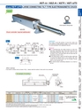
Worm wheelWormIndicating plateScaled ring180Main unit170 180 170100IntermediateshaftIntermediatetilting baseTilting shaftTilting baseKey width 8 テ・depth 5100 200200200170270840750 9040マ・0マ・040 40LeadshaftMain unit Main unitLLep1 L 1L 1L 2L 1(The above figure shows 3 standard units connected.)Fig. 1Fig. 2An example of mountingEnvironmentallyfriendlyModel KET-UTS LARGE CONNECTING TILT TYPE ELECTROMAGNETIC CHUCK窶サThe chuck controllers in this table are for single unit and when two or more units are connected, use 窶彡urrent テ・number of units connected窶・to select a suitable model.窶サIf the magnetic force needs not be adjusted, use ES-M.窶サThe chuck controller and clamp parts are not included. The KANETEC chucks work best when a KANETEC chuck controller is used.窶サThe above models include the main unit, right/left tilting bases, lead shaft and tilting shaft.窶サThe face plate of KET-UTJFS types is of split construction and no magnetic force may be generated in the center part.KET-UTFSIntermediate tilting baseChuck controller required additionally・サApplication・スThis model is used with grinders of wood slice cutters andmost suitable for angle grinding of edges. It can also be usedfor uniform grinding in the longitudinal direction.・サFeatures・ス笳就s a connecting type, this model consists of a main unit,lead shaft, intermediate shaft, tilting shaft, tilting base andintermediate tilting base. When one unit is used, it is usedas shown in Fig. 2 and when three units are used, they areconnected as shown in Fig. 1.笳就s the tilting torque is large, the shaft has been made longto increase the reduction ratio on your machine side. (Thescaled ring and tilting device are not included. Providethem on your machine side.)笳週he chuck-to-chuck connecting clearance is as small as40 mm.縲・hen ordering縲迂f you want to connect units as shown in Fig. 1, please order the number of main units to be connected・サmm・・n・会シスModel Nominal SizeWork Face Pole pitch LengthVoltage Current Mass ElectroChuck Master RemarksL? Le P L?KET-20100UTFS 200・・.87・嘉・000・・9.3・・1000・・9.3・・920・・6.2・・8・・・・4・会シ・.10・俄サPitch variesaccordingto places.1340・・2.7・・0 VDC0.72A Approx.305kg/ 672 lbES-M103BES-M305BEH-V305AEH-VE305A窶サ For types with a combination of縲a rectifi er and demagnetizer, see縲pages of 窶廚huck Controllers.窶扛ET-20120UTFS 200・・.87・嘉・200・・7.2・・1200・・7.2・・1120・・4.0・・1540・・0.6・・0.90A Approx.355kg/ 782 lbKET-20140UTFS 200・・.87・嘉・400・・5.1・・1400・・5.1・・1320・・1.9・・1740・・8.5・・1.00A Approx.400kg/ 881 lbKET-20150UTFS 200・・.87・嘉・500・・9.0・・1500・・9.0・・1420・・5.9・・1840・・2.4・・1.25A Approx.430kg/ 948 lbKET-20160UTJFS 200・・.87・嘉・600・・2.9・・1600・・2.9・・1520・・9.8・・1940・・6.3・・1.35A Approx.445kg/ 981 lbKET-20170UTJFS 200・・.87・嘉・700・・6.9・・1700・・6.9・・1620・・3.7・・2040・・0.3・・1.33A Approx.465kg/1025 lbP17?P20KET-U / KEZ-H / KETV / KET-UTS12CHUCKCONTROLLERSPERMANENTMAGNETIC CHUCKSPERMANENTELECTROMAGNETIC CHUCKSBLOCKSFOR MCVACUUMCHUCKSPROMELTA*SYSTEMSINE BARCHUCKSHOLDINGTOOLSBLOCKS, HOLDERS,MINI CHUCKSMEASURINGTOOL HOLDERSMAGNETICTOOLSMAGNETICHOLDERSELECTROMAGNETICCHUCKS